- 您现在的位置:买卖IC网 > Sheet目录1219 > HC5514XEVAL3 (Intersil)EVAL BOARD TI CODEC MOTHER BOARD
�� �
�
�Application� Note� 9871�
�The� evaluation� of� all� 9� tests� require� the� following� equipment:�
�a� 600� ?� (1� watt,� 1%)� load,� a� 1777� ?� (2� watt,� 1%)� load,� a�
�26.1k� ?� (1/4� watt,� 1%)� RDC_RAC� resistor,� two� sine� wave�
�generators,� an� AC/DC� volt� meter,� three� external� supplies�
�(V� BH� ,� V� BL� ,� V� CC� ),� a� dual� channel� storage� oscilloscope,� a�
�9.� Con?gured� the� SLIC� in� the� reverse� active� state�
�(C3� =� 1,� C2� =� 1,� C1� =� 0).� Measure� the� supply� currents� and�
�compare� to� those� in� Table� 1.� Repeat� step� 8.�
�TABLE� 1.� SUPPLY� CURRENTS� AND� POWER� DISSIPATIONS�
�telephone,� BNC� to� banana� adaptor,� a� battery� backed� AC�
�SUPPLY�
�SUPPLY�
�POWER�
�source� and� a� dynamic� signal� analyzer.�
�LOGIC�
�STATE�
�R� L�
�(� ?� )�
�VOLTAGE�
�(DC)�
�CURRENT�
�TYP� (mA)�
�DISSIPATION�
�(mW)�
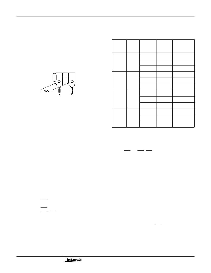
�Application� Tip:� When� terminating� tip� and� ring,� it� is� handy� to�
�assemble� terminators� using� a� Pomona� MDP� dual� banana�
�plug� connector� as� the� terminating� resistor� receptacle.� Refer�
�to� Figure� 1� for� details.�
�Forward�
�Active�
�Onhook�
�Without�
�Load�
�V� BH� =� -48V�
�V� BL� =� -24V�
�0.8�
�0.0001�
�38.4�
�0.0024�
�V� CC� =� +5V�
�2.91�
�14.5�
�Forward�
�Offhook�
�V� BH� =� -48V�
�30.0�
�1440�
�A�
�B�
�Active�
�with�
�600� ?�
�V� BL� =� -24V�
�2.68�
�64.3�
�Load�
�V� CC� =� +5V�
�4.2�
�21�
�600� ?�
�Reverse�
�Onhook�
�V� BH� =� -48V�
�0.85�
�40.8�
�Active�
�Without�
�FIGURE� 1.� TERMINATION� ADAPTER�
�Load�
�V� BL� =� -24V�
�V� CC� =� +5V�
�0.0001�
�2.97�
�0.0024�
�14.8�
�Using� the� termination� shown� in� Figure� 1� provides� an�
�unobtrusive� technique� for� terminating� tip� and� ring� while� still�
�providing� access� to� both� signals� using� the� banana� jack�
�feature� of� the� MDP� connector.� Posts� are� also� available� that�
�?t� into� holes� A� and� B,� providing� a� solderable� connection� for�
�Reverse�
�Active�
�Offhook�
�with�
�600� ?�
�Load�
�V� BH� =� -48V�
�V� BL� =� -24V�
�V� CC� =� +5V�
�29.74�
�1.9�
�4.27�
�1427�
�45.6�
�21.3�
�the� terminating� resistor.�
�Test� #1,� Power� Supply� Current� Veri?cation�
�A� quick� check� of� the� evaluation� board� and� sample� is� to�
�measure� the� supply� currents.� The� readings� should� be� similar�
�to� the� values� listed� in� Table� 1.� The� measurements� can� be�
�made� using� a� series� ammeter� on� each� supply,� or� power�
�supplies� with� current� displays.�
�Setup�
�1.� Connect� the� power� supplies� to� the� Evaluation� board.�
�2.� Set� V� BH� to� -48V,� V� BL� to� -24V� and� V� CC� to� +5V.�
�3.� Verify� the� thermal� management� switch� (S9,� located�
�towards� the� top� middle� of� the� board)� is� in� the� V� BL� =� V� BL�
�position.�
�4.� Verify� that� the� POL/REV� switch� S4� (lower� right� hand� side�
�of� the� board)� is� in� either� the� 10ms� or� 20ms� position.�
�5.� Con?gure� the� SHD� switch� (S5)� to� be� in� the� JACK� position.�
�This� will� allow� an� accurate� reading� of� the� V� CC� current� by�
�removing� the� SHD� LED� current.�
�6.� Con?gure� the� GKD_LVM� switch� (S6)� to� be� in� the� BNC�
�position.� This� will� allow� an� accurate� reading� of� the� V� CC�
�current� by� removing� the� GKD_LVM� LED� current.�
�7.� Con?gure� the� SLIC� to� be� in� the� Forward� Active� State�
�(C3� =� 0,� C2� =� 1,� C1� =� 0).� Measure� the� supply� currents� and�
�compare� to� those� in� Table� 1.�
�8.� Terminate� tip� and� ring� with� a� 600� ?� load.� Measure� the�
�supply� currents� and� compare� to� those� in� Table� 1.� Remove�
�600� ?� load.�
�2�
�Test� #2,� Normal� Loop� Feed� Veri?cation�
�This� test� veri?es� the� correct� tip� and� ring� voltages� in� both�
�onhook� and� offhook� forward� active� and� reverse� active� states.�
�Loop� current� and� ground� key� detect� are� also� veri?ed� via� the�
�onboard� SHD� and� GKD_LVM� LEDs.�
�Discussion�
�The� HC5514� is� designed� to� have� its� most� positive� 2-wire�
�terminal� (tip� in� the� forward� active� state� and� ring� in� the�
�reverse� active� state)� ?xed� at� a� set� voltage.� This� set� voltage�
�depends� upon� the� required� overheads� for� the� application.�
�The� most� negative� 2-wire� terminals� voltage� is� dependent�
�upon� the� load� across� tip� and� ring� and� the� programmable�
�current� limit.�
�The� tip� and� ring� voltages� for� various� loop� resistances� are�
�shown� in� Figure� 2.� The� tip� voltage� remains� relatively�
�constant� as� the� ring� voltage� moves� to� limit� the� loop� current�
�for� short� loops.�
�When� power� is� applied� to� the� SLIC,� a� loop� current� will� ?ow�
�from� tip� to� ring� through� the� 600� ?� load.� Loop� current�
�detection� occurs� when� this� loop� current� triggers� an� internal�
�detector� that� pulls� the� output� of� SHD� low,� illuminating� the�
�LED� through� the� +5V� supply.�
�发布紧急采购,3分钟左右您将得到回复。
相关PDF资料
HC55185EVAL2
EVALUATION PLATFORM HC55185+T
HE1015
BOOT CIRCUIT BREAKER 1POLE CLEAR
HE1020
BOOT CIRCUIT BREAKER 2POLE CLEAR
HE1050
BOOT CIRCUIT BREAKER 3POLE CLEAR
HE1070
BOOT CIRCUIT BREAKER 3POLE CLEAR
HFW30R-1STE1
HFW30R-1STE1-FFC/FPC CONN
HFW30S-2STE1
HFW30S-2STE1-USING HFW-P5SL
HHG
FUSEHOLDER AUTO INLINE FOR ATC
相关代理商/技术参数
HC5515
制造商:INTERSIL 制造商全称:Intersil Corporation 功能描述:ITU CO/PABX SLIC with Low Power Standby
HC5515_06
制造商:INTERSIL 制造商全称:Intersil Corporation 功能描述:ITU CO/PABX SLIC with Low Power Standby
HC55150
制造商:INTERSIL 制造商全称:Intersil Corporation 功能描述:Low Power Universal SLIC Family
HC55150CB
制造商:Rochester Electronics LLC 功能描述:LOW PWR SLIC,POL REV/METERING,55DB BALANCE - Bulk
HC55150CBZ
功能描述:电信线路管理 IC LW PWR SLIC POLV/MTRING 55DB RoHS:否 制造商:STMicroelectronics 产品:PHY 接口类型:UART 电源电压-最大:18 V 电源电压-最小:8 V 电源电流:30 mA 最大工作温度:+ 85 C 最小工作温度:- 40 C 安装风格:SMD/SMT 封装 / 箱体:VFQFPN-48 封装:Tray
HC55150CM
制造商:Rochester Electronics LLC 功能描述:LOW PWR SLIC,POL REV/METERING,55DB BALANCE - Bulk
HC55150CMZ
功能描述:电信线路管理 IC LW PWR SLIC POLV/MTRING 55DB RoHS:否 制造商:STMicroelectronics 产品:PHY 接口类型:UART 电源电压-最大:18 V 电源电压-最小:8 V 电源电流:30 mA 最大工作温度:+ 85 C 最小工作温度:- 40 C 安装风格:SMD/SMT 封装 / 箱体:VFQFPN-48 封装:Tray
HC55151
制造商:INTERSIL 制造商全称:Intersil Corporation 功能描述:Low Power Universal SLIC Family